
Check units and compare the display with a known measurement before changing CT-22 settings. Speed, distance, and battery bars use different parameters. Save the original values first, and keep the supplier examples separate from your installed display configuration.
Advanced: Speed and Distance Parameters
This is a documented parameter reference. It does not supply verified ONYX defaults, a tested correction formula, or a recommended replacement value. A worked calibration example requires measurements from an identified display and pulse source; none is established here.
Check Accuracy Before Editing
- Confirm a compatible, stable pulse signal and the selected MPH / km/h units.
- Photograph or record the existing parameters.
- Compare displayed speed with an independent reference at several steady speeds.
- Check trip distance separately over a measured route.
- Record conditions and results before deciding whether a parameter change is warranted.
Use the GPS performance-meter guide for comparison methods. One matching speed reading does not verify the full range. A stationary, jumping reading should be investigated as a signal problem before treating it as a calibration error.
Record Existing Settings
Record the bike, display label or revision if available, controller, pulse source, and units alongside this table. Fill in the original values before editing; no ONYX defaults are implied by the blank cells.
| Parameter | Original value | New value | Reason for change | Result after restart |
|---|---|---|---|---|
| 0: speed reference | - | - | - | - |
| 1: distance reference | - | - | - | - |
| Other parameter: record its label | - | - | - | - |
Enter Parameter Settings
Sources: bilingual manual, pages 3-5 , and Kelly manual, pages 2-3 .
- With display power off, hold the lower SET button and apply power.
- The documented screen is
P-0000, with the rightmost digit flashing. - Tap SET to increase the selected digit from 0-9.
- Hold SET to move to the next higher digit.
- Complete the digits for 6610 to enter parameter settings.
6610 opens a menu containing speed, distance, and battery-gauge parameters. The separate codes 8810 and 6810 clear or set cumulative distance; the bilingual manual also states that setting cumulative distance clears the trip. They are not part of routine speed adjustment.
Speed and Distance Reference Values
| Documented example | Meaning |
|---|---|
| 0-0420 | Speed reference: 420Hz corresponds to 60 km/h |
| 1-0420 | Distance reference, expressed using the frequency corresponding to 60 km/h |
These are examples, not verified ONYX factory values. The bilingual manual, page 5, prints an editable range of 0-9999; Kelly, page 3, prints 0-999. The documents do not resolve the actual installed firmware’s limits.
The bilingual manual, pages 9-10, describes the menu controls:
- Short press: advance to the next parameter while viewing the menu.
- Long press: enter editing of the selected parameter.
- While editing: short presses increment the flashing digit; long presses move left between digits.
- After editing the highest digit: long press to finish that parameter.
It describes exiting with a further short press at J-0030. For a speed-only edit, it also describes completing parameter 0, advancing to parameter 1, then powering off and restarting. Confirm that any edited value was retained.
Editing the stored frequency for the 60 km/h reference can switch the unit configuration to metric, according to the manuals. Recheck units, speed, and distance afterward. Determine the correction method and adjustment direction for the actual display before changing a value; this guide does not infer an ONYX calibration rule from the example frequency.
Battery-Gauge Parameters
The menu also includes battery thresholds and timing. No verified 72V ONYX threshold set is provided here. Preserve existing values unless the actual battery configuration and applicable display behavior are established. The high-voltage examples are available in the collapsed supplier reference below.
Supplier Specifications and Examples
These references describe supplier documents, not measurements of an identified ONYX display. Diagram 4 summarizes the engineering-sheet tables; diagram 6 shows its generic circuits.
Dimensions and Materials
| Item | Source-sheet specification |
|---|---|
| Width | 183.3 mm |
| Height | 87.3 mm |
| Depth | 78.6 mm |
| Mounting-stud spacing | 66 mm |
| Mounting studs | M6 × 16.5 |
| Harness dimension shown on engineering sheet | 300 mm |
| Wire cross-section | 0.5 mm² |
| Panel | Transparent PC |
| Lining plate | ABS |
| Bottom housing | ABS |
| Unspecified dimensions | Refer to the source 3D model |
| Unspecified dimensional tolerances | GB/T 1804-v |
The drawing also references Q/HTR-2007 for the harness, QC/T 417.1 through QC/T 417.5 for connectors/terminals, JB/T 8139 for wire, and QC/T 727 for instrument performance. These are source-sheet references, not an independent certification of the installed display.
Supplier Voltage Ratings
The SiAECOSYS instrument manual, pages 6-7 lists a CT-22 configuration with a 72V nominal rating and 33-144V supply range. Its wiring table also uses high-voltage labels and return descriptions that differ from the annotated harness. These entries do not establish the supply rating or wiring of every ONYX or replacement display. Check the actual unit before changing voltage.
Supplier speed-signal reference table: not an ONYX calibration curve
These are the engineering sheet’s indicated-speed ranges. They are not a measured ONYX calibration curve.
| Frequency (Hz) | Displayed speed (km/h) |
|---|---|
| 140 | 20-21 |
| 280 | 40-42 |
| 420 | 60-63 |
| 560 | 80-84 |
| 700 | 100-105 |
| 840 | 120-126 |
| 980 | 140-147 |
| 1120 | 160-168 |
| 1260 | 180-190 |
Supplier battery examples: not 72V ONYX settings
Programmable Gauge Parameters
These high-voltage examples come from the bilingual CT-22 manual, pages 5-8 . Voltage entries are scaled by ten: 1320 means 132V. Do not copy them to a 72V ONYX display or scale them into assumed ONYX defaults.
| Parameter | Example | Documented role |
|---|---|---|
| 2 | 1320 | Charging, 20% voltage point |
| 3 | 1370 | Charging, 40% voltage point |
| 4 | 1420 | Charging, 60% voltage point |
| 5 | 1460 | Charging, 80% voltage point |
| 6 | 1520 | Charging, 100% voltage point |
| 7 | 1320 | Discharging, 20% voltage point |
| 8 | 1370 | Discharging, 40% voltage point |
| 9 | 1420 | Discharging, 60% voltage point |
| A | 1460 | Discharging, 80% voltage point |
| B | 1520 | Discharging, 100% voltage point |
| C | 0300 | Full-scale gauge damping time, 300 seconds in this example |
| D | 1250 | Charging, 0% voltage point |
| E | 1250 | Discharging, 0% voltage point |
| F | 0001 | Charging-memory percentage, 1% in this example |
| R | 0 | Reserved low-voltage warning function; unavailable on the board version named in the manual |
| J | 0030 | Battery-level judgment time, 30 seconds in this example |
Source correction note: the 100% labels for parameters 6 and B and the 0% label for E follow the bilingual manual (pages 6-8). Kelly’s English table prints 40% for those entries. The labels above follow the identified bilingual source; they are not silently corrected transcriptions of Kelly.
The bilingual manual, page 8, mentions a 48-second hold during operation to clear charging memory without clearly naming the button in that entry; Kelly, page 4, specifies SET. This is not a trip-reset operation. Preserve existing settings where behavior is unresolved.
Engineering-Sheet Battery Bars
The original engineering sheet labels instrument power DC 144V, indicator power 12V, and speed input as an external digital signal. Its battery-bar table is reproduced below for reference, not as a 72V ONYX configuration.
| Supply voltage (V) | Battery bars |
|---|---|
| <132 | 1, flashing |
| 132-134.5 | 2 |
| 134.5-137 | 3 |
| 137-139.5 | 4 |
| 139.5-142 | 5 |
| 142-144 | 6 |
| 144-146 | 7 |
| 146-149 | 8 |
| 149-152 | 9 |
| >152 | 10 |
The interval boundaries reproduce the source notation; behavior at shared endpoints is not specified here.
The source describes bars decreasing only during operation, with a 30-second decision time and a reduction rate of one bar per 15 seconds. After power cycling, the bar count is recalculated from its voltage table. The parameter manual also documents programmable gauge thresholds and timing, so these values should not be assumed for every unit.
Original generic diagram: compare source wiring before use
This original image is retained for source comparison. Its generic wire assignments differ from the annotated harness reference ; it is not an ONYX installation pin map.

Manuals and Source Notes
Page references use PDF page order. The locally hosted filenames identify downloads on this site; they do not establish ONYX authorship or approval of the underlying supplier documents.
| Document | Publisher / identification | Use in this guide |
|---|---|---|
| Bilingual CT-22 button manual | CT-22 Speedometer Button Function; V1.1, January 27, 2018; hosted here as “ONYX Display Manual” | Clock: p. 1; units and conflicting trip reset: p. 2; parameters: pp. 3-10; cumulative-distance setting: pp. 10-11 |
| Kelly CT-22 button manual | CT-22 Speedometer Button Instruction; V1.1, January 27, 2018; hosted by Kelly | Alternative button instructions: p. 2; parameters: pp. 3-5 |
| Original CT-22 engineering diagram | Single-sheet supplier drawing; revision not established here; hosted as “ONYX Display Diagram” | Generic dimensions, wiring, speed table, and 144V battery examples |
| Kelly-hosted engineering drawing | Supplier drawing hosted by Kelly; revision not established here | Additional generic drawing reference; not verification of the annotated harness |
| Annotated harness illustration | Reference reproduced in diagram 2; bike and display revision not identified | Source of the A/B labels and harness tables; viewing side and individual test results remain undocumented |
| SiAECOSYS instrument manual | SiAECOSYS; revision/date not established here | CT-22 specifications and a separate wiring configuration: pp. 6-7 |
| SiAECOSYS accessories manual | SiAECOSYS, Other Accessories Manual; hosted by Manuals.plus; revision/date not established here | Fardriver Conventional + CT22 harness listing: p. 8 |
| SiAECOSYS Fardriver parameter manual | SiAECOSYS; revision/date not established here | Hardware distinctions and speedometer-output options; select the section applicable to the actual controller |
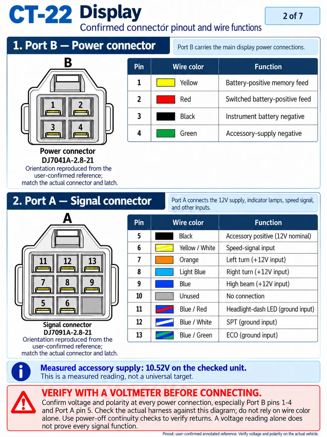
The harness assignments and supplier specifications above are attributed references. An oriented connector photograph, an identified ONYX display with measured settings, and a tested conversion would be needed to resolve the remaining installation-specific questions.