
Use the CT-22 wiring reference to identify the documented power, return, speed, and indicator circuits. Check the actual harness before connecting anything: the source diagrams do not establish every connector viewing detail or display revision.
CT-22 Diagram Images
Select a thumbnail to enlarge it, then use the viewer controls to browse or zoom. Diagram numbers match the labels in the images.
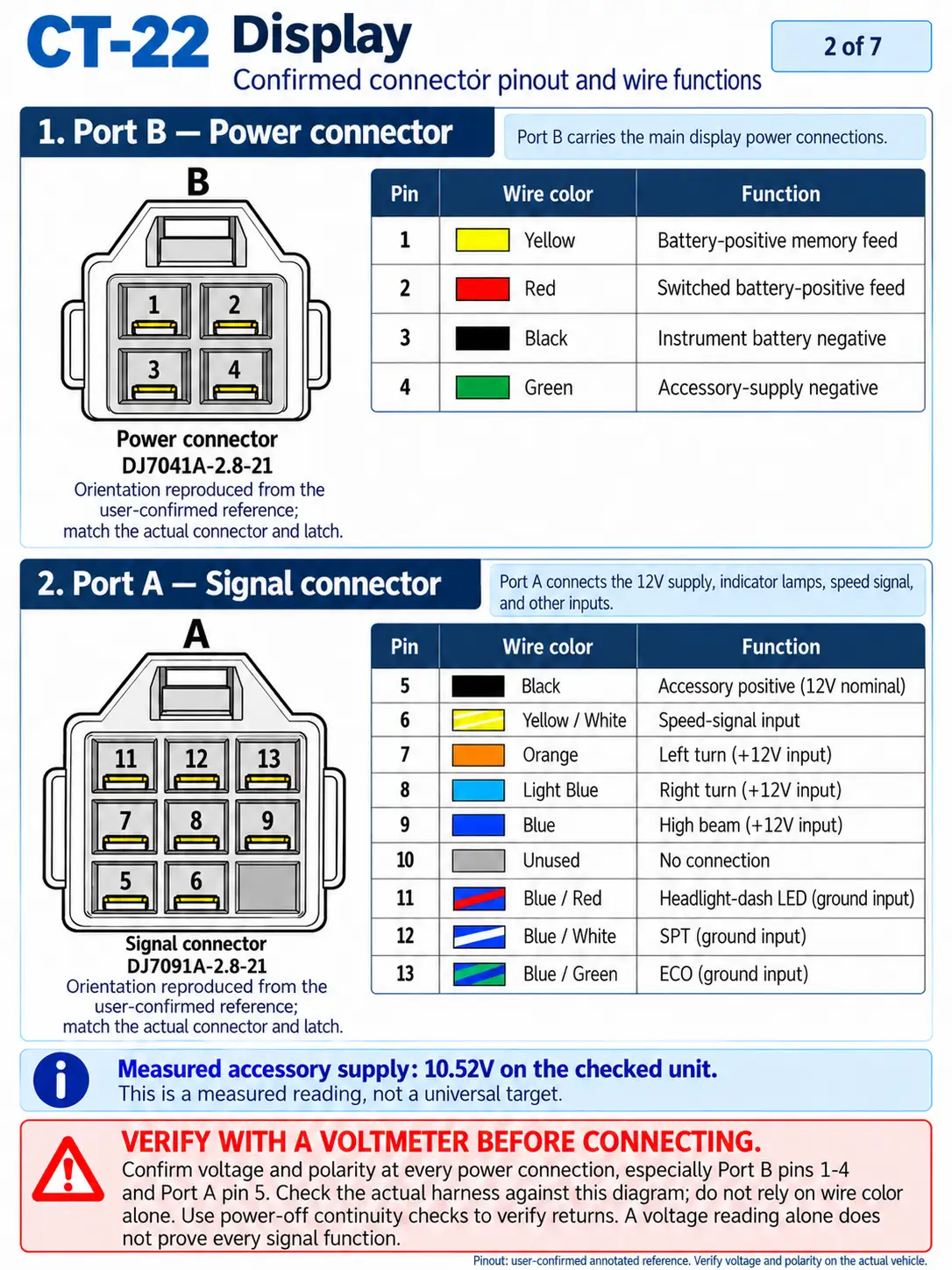
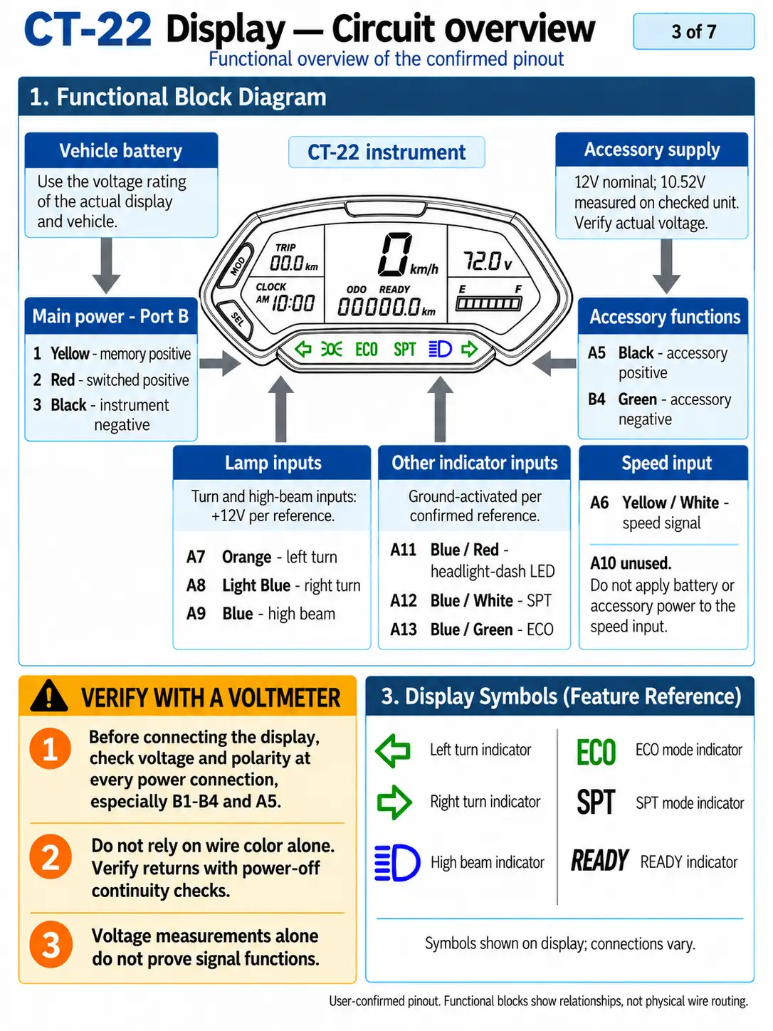
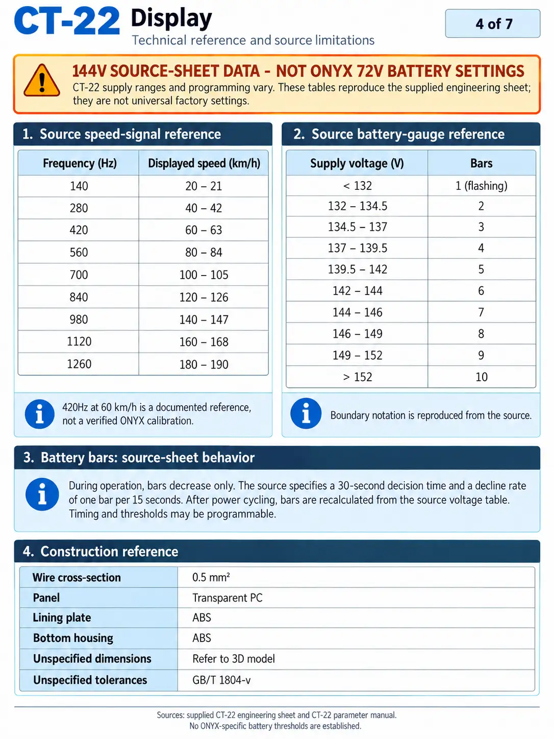
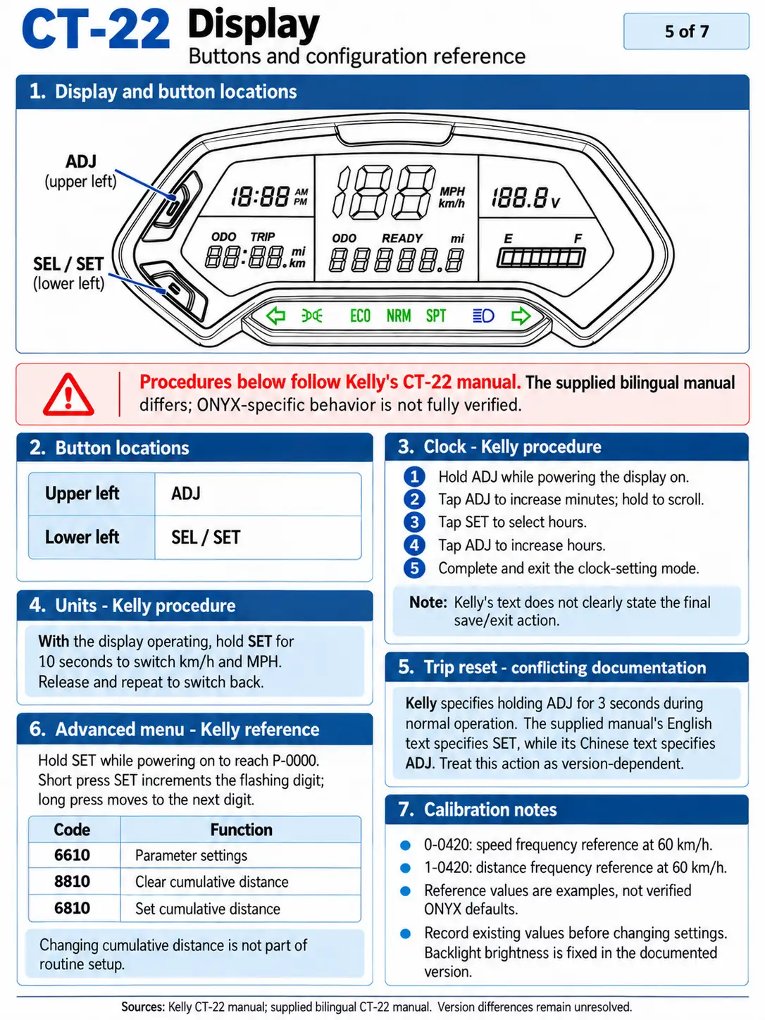
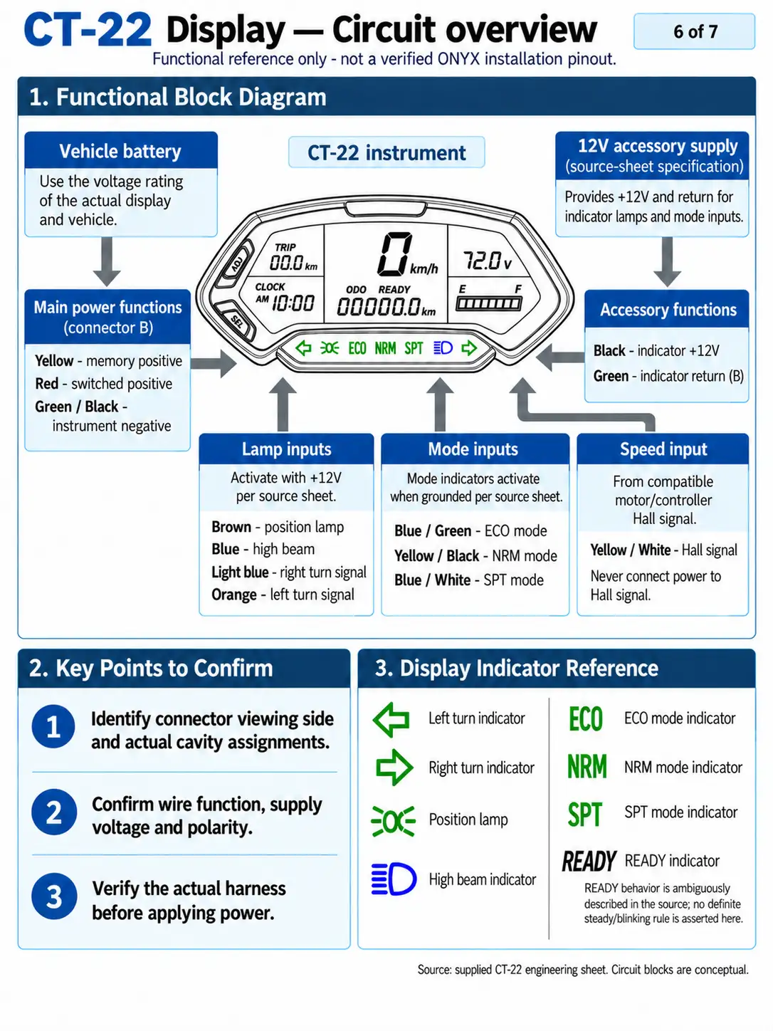
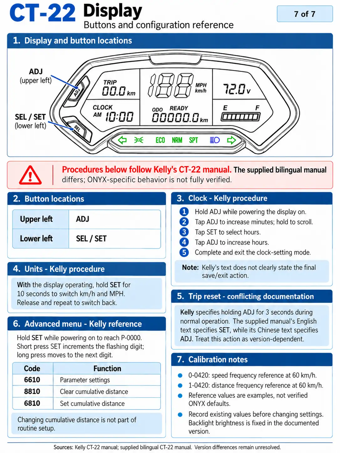
Diagrams 2 and 3 reproduce the annotated harness reference; their use of “confirmed” does not establish independent testing of every connection. Diagram 4 contains 144V supplier examples, not 72V ONYX settings. Diagram 5 is an earlier illustration with a different screen layout; use diagrams 1 and 7 for the layout described here. Diagram 6 shows generic source-sheet circuits with different wiring assignments. Use the written source notes below when comparing these references.
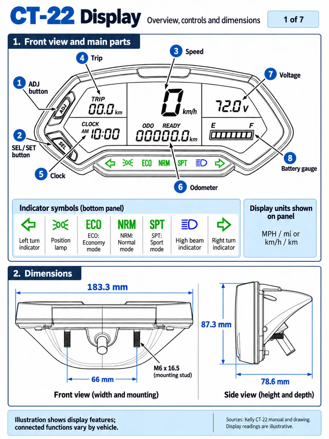
Annotated Harness Reference
Evidence, Labels and Connector View
The assignments below are transcribed from the annotated reference reproduced in diagram 2. Diagram 3 summarizes its circuit functions. The reference calls the pinout “confirmed,” but this article does not document the bike’s model year, display revision, original versus replacement status, or individual continuity and function-test results. Treat it as a reference to compare with the actual harness.
A6 means label 6 on reference connector A; B1 means label 1 on reference connector B. The numbers are used here as drawing reference labels. Their correspondence to any molded cavity numbers has not been established. Connector A’s labels run from 5 to 13 because they follow the reference’s numbering across both connectors.
Connector viewing side is unresolved. The tables reproduce diagram 2 with the latch at the top, but the available reference does not explicitly establish mating-face versus wire-side viewing. Those views reverse left and right. Do not use the position tables as a connection-ready pin map until the viewing side and assignments have been established on the physical connector. No matching, oriented connector photograph is available in this guide.
Before connecting, verify supply voltage, polarity, and the appropriate return for each circuit, especially B1-B4 and A5. Perform continuity checks only with power disconnected. A voltmeter reading alone does not prove a signal function or pulse characteristic; speed-input testing may require a frequency-capable meter or oscilloscope.
Port B: Power Connector
Reference connector designation: DJ7041A-2.8-21.
| Reference label | Wire color | Assigned function in diagram 2 |
|---|---|---|
| B1 | Yellow | Battery-positive memory feed |
| B2 | Red | Switched battery-positive feed through ignition / electric lock |
| B3 | Black | Instrument battery negative |
| B4 | Green | Accessory-supply negative |
Drawing positions, latch at top; physical viewing side unverified:
| Position | Left cavity | Right cavity |
|---|---|---|
| Top row | B1 | B2 |
| Bottom row | B3 | B4 |
Port A: Signal and Indicator Connector
Reference connector designation: DJ7091A-2.8-21.
| Reference label | Wire color | Assigned function / activation in diagram 2 |
|---|---|---|
| A5 | Black | Accessory positive, 12V nominal |
| A6 | Yellow / White | Speed-signal input |
| A7 | Orange | Left-turn indicator, positive input |
| A8 | Light Blue | Right-turn indicator, positive input |
| A9 | Blue | High-beam indicator, positive input |
| A10 | Unused | Blank lower-right cavity in the reference |
| A11 | Blue / Red | Headlight-dash LED, ground-activated input |
| A12 | Blue / White | SPT indicator, ground-activated input |
| A13 | Blue / Green | ECO indicator, ground-activated input |
Drawing positions, latch at top; physical viewing side unverified:
| Position | Left cavity | Center cavity | Right cavity |
|---|---|---|---|
| Top row | A11 | A12 | A13 |
| Middle row | A7 | A8 | A9 |
| Bottom row | A5 | A6 | A10: unused |
The reference describes the accessory circuit as 12V nominal. Diagrams 2 and 3 also print an accessory-voltage measurement without identifying the measurement points, operating state, or unit. That reading is not adopted here as a diagnostic target.
Circuit Functions
| Circuit | Reference connections | Purpose |
|---|---|---|
| Main instrument power | B1, B2, B3 | Memory feed, switched feed, and battery return |
| Accessory power | A5, B4 | Indicator supply and its return |
| Turn / high-beam inputs | A7, A8, A9 | Positive-activated indicators |
| Other indicator inputs | A11, A12, A13 | Ground-activated headlight-dash, SPT, and ECO indications |
| Speed input | A6 | Compatible speed pulses |
Diagram 3 is a functional explanation, not a physical routing drawing. Keep instrument and accessory returns identified separately; do not assume they are interchangeable or that every input comes directly from the controller.
Differences from Generic Supplier Wiring
Diagram 6 follows the generic engineering sheet. Its assignments differ from diagram 2:
| Function | Annotated harness reference | Generic engineering-sheet reference |
|---|---|---|
| Instrument negative | B3, Black | Green / Black |
| Speed input | A6, Yellow / White | Yellow / White, listed as No. 10 in the sheet’s table |
| Position / headlight-dash | A11, Blue / Red, ground-activated | Brown position-light input, positive-activated |
| NRM input | No dedicated connection identified | Yellow / Black |
| ECO input | A13, Blue / Green | Blue / Green, listed as No. 11 |
| SPT input | A12, Blue / White | Blue / White, listed as No. 13 |
The generic sheet’s table numbers must not be substituted for the annotated connector labels. See the original engineering diagram when comparing sources.
Fardriver Controller Compatibility
Supplier documentation shows a CT-22 integration path: the SiAECOSYS accessories manual, page 8 lists a Fardriver Conventional + CT22 harness. This is not evidence of a tested installation for each ONYX display, Fardriver model, firmware, and harness combination.
Here, retaining the display means preserving the functions below through suitable power and signal connections. This guide does not document a completed ONYX conversion demonstrating all of them.
| Function to retain | Requirement to establish for the installation |
|---|---|
| Speed and distance | Compatible pulse source, electrical signal levels and reference, and matching display parameters |
| Power and voltage reading | Correct feeds, returns, and rating of the actual display |
| Turn / high-beam indications | Separate compatible lighting-signal connections |
| ECO / SPT indications | Appropriate ground-activated input wiring or interface for the annotated harness |
| Clock and trip controls | Local button operation, subject to the documentation conflicts above |
The generic CT-22 drawing identifies a motor/controller Hall signal as the speed source. A controller-generated output is an alternative only after its electrical characteristics and configuration are checked. A one-line serial or analog speedometer output is not automatically interchangeable with a Hall pulse input.
The SiAECOSYS Fardriver parameter manual describes pulse-output options and hardware-dependent assignments. Use the sections for the actual controller hardware; this guide does not prescribe a universal pin, wire color, or setting. An encoder installation also needs an appropriate pulse source or interface rather than an assumed motor Hall connection.
Controller mode selection does not establish display-indicator wiring. See Fardriver display settings and telemetry for the distinction between display configuration and controller measurement calibration. If the conversion changes battery voltage, establish both the display’s supply rating and suitable gauge configuration before connecting it.
Manuals and Source Notes
Page references use PDF page order. The locally hosted filenames identify downloads on this site; they do not establish ONYX authorship or approval of the underlying supplier documents.
| Document | Publisher / identification | Use in this guide |
|---|---|---|
| Bilingual CT-22 button manual | CT-22 Speedometer Button Function; V1.1, January 27, 2018; hosted here as “ONYX Display Manual” | Clock: p. 1; units and conflicting trip reset: p. 2; parameters: pp. 3-10; cumulative-distance setting: pp. 10-11 |
| Kelly CT-22 button manual | CT-22 Speedometer Button Instruction; V1.1, January 27, 2018; hosted by Kelly | Alternative button instructions: p. 2; parameters: pp. 3-5 |
| Original CT-22 engineering diagram | Single-sheet supplier drawing; revision not established here; hosted as “ONYX Display Diagram” | Generic dimensions, wiring, speed table, and 144V battery examples |
| Kelly-hosted engineering drawing | Supplier drawing hosted by Kelly; revision not established here | Additional generic drawing reference; not verification of the annotated harness |
| Annotated harness illustration | Reference reproduced in diagram 2; bike and display revision not identified | Source of the A/B labels and harness tables; viewing side and individual test results remain undocumented |
| SiAECOSYS instrument manual | SiAECOSYS; revision/date not established here | CT-22 specifications and a separate wiring configuration: pp. 6-7 |
| SiAECOSYS accessories manual | SiAECOSYS, Other Accessories Manual; hosted by Manuals.plus; revision/date not established here | Fardriver Conventional + CT22 harness listing: p. 8 |
| SiAECOSYS Fardriver parameter manual | SiAECOSYS; revision/date not established here | Hardware distinctions and speedometer-output options; select the section applicable to the actual controller |
The harness assignments and supplier specifications above are attributed references. An oriented connector photograph, an identified ONYX display with measured settings, and a tested conversion would be needed to resolve the remaining installation-specific questions.